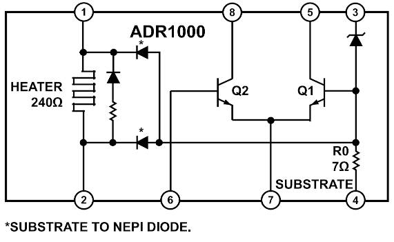
Called ADR1000 (right), the nominally 6.62V part is a pin-compatible replacement for the LTZ1000 (below), and like it includes a buried Zener reference, a heater for temperature stabilization and a temperature sensor.
As with the earlier part, external circuitry is used to manage the inernal parts.
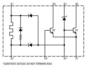
Venerable LTZ1000, originally a Linear Tech design
Headline parameters for the ADR1000 are: 6.62±0.05V initial output, 0.5ppm/year typical drift (after initial 3,000h), 0.14ppm (0.9µV) peak-peak noise, <0.2ppm/°C drift.
These compare with: 7.2-0.2+0.3V initial output, 0.05ppm/°C, ~1.2µVpp noise and 2µV/√kHr stability for the LTZ1000. The LTZ1000A has improved (400°C/W) internal thermal insulation.
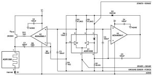 With the recommended external cicuitry (right) and the correct layout are needed to get the temperature coefficient and long-term drift figures above.
Operation is over -40 to +125°C (LTZ1000 is -55°C), with the temperature set point of the heater 10°C higher than the maximum ambient temperature to provide optimum Zener stability.
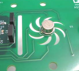
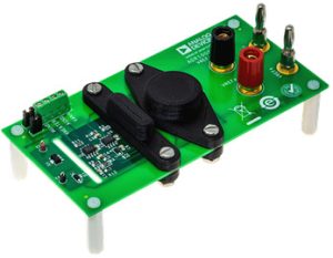 There is an evaluation kit in which the reference IC is centered in a PCB cut-out to weaken temperature and humidity coupling from the PCB. There are also slots in the PCB to keep heat from coupling from the heater transistor to the control circuit, and between the IC and nearby resistors.
 “The heater temperature is set by the standard 13k:1k divider as with the old LTZ1000,” according to ADI. However, the ADR1000 runs about 5°C warmer (75°C) than the LTZ1000 (70°C) due to the slightly lower voltage of the ADR1000 applied to the divider.”
Web pages:
ADR1000 and its eval kit


