Too long, is the answer (please be gentle, I do not have a Spice simulation background 🙂
LTspice has a way to model electromechanical switches, which I have occasionally tried to use to simulate dc-dc converters without all the hassle of setting up mosfets and appropriate driver circuits.
But it has never worked for me until today
The switches are a little odd in that they do not carry their own timing. Instead, they are a sort of relay – with contacts controlled by voltage levels on the pair of terminals on the side of the symbol (during the simulation, the control terminals are treated as completely electrically isolated from the switch terminals).
And it worked (right) – currents through the two switches
Getting the appropriate symbol and setting it up is not a simple drag-n-drop process like it is for capacitors, for example, and it is not even as slightly-less-simple as selecting an npn transistor from the ‘component select’ menu.
Instead, you have to select ‘SW’ from the ‘component select’ menu and drop that, and then remember to write a short script (see below).
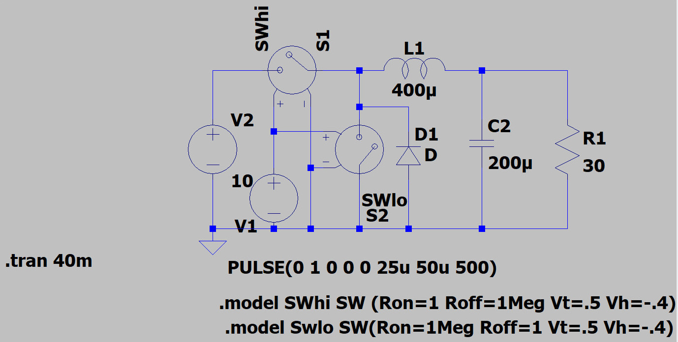
 Switches arrive with the name ‘SW’, and if you have more than one in your circuit you have to change that ‘SW’ to unique names (right click on the symbol after placement) – I used SWhi and SWlo in the my example (left).
When you connect them up, it seems that you have to connect the negative control terminal to LTspice’ triangular ‘ground’ symbol (left), then you have to connect a voltage source between that same ‘ground’ net to the ‘+’ symbol on the switch.
That troubling script
The script is written by pressing the keyboard ‘s’ key, which opens up a dialog box, and accurately typing in a string like the ones in the above circuit diagram. The parameters are contact on and off resistance, then threshold and hysteresis for the control voltage (note the minus symbol in front of the hysteresis value).
I used the threshold and hysteresis from an ADI (was LT) example, and then (using right click on the voltage source symbol) set the voltage source to ‘pulse’ mode and a 0V to 1V swing with appropriate timing.
It is apparently possible to select normally-open and normally-closed switches (somehow), but on a whim I tried swapping the ‘on’ and ‘off resistance values for the anti-phase synchronous rectifier switch, and this worked like a charm (see circuit diagram).
Hats off to Analog Devices for keeping LTspice downloadable and free


