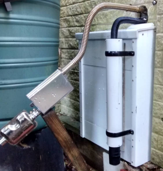
I finally got around to installing over the cold snap before Christmas, putting the heater unit inside the workshop (right) and the exhaust, air intake, fuel tank, pump and fuel filter outside.
Disclaimer and safety note: What you do to your diesel heater is your affair. If you don’t know what you are doing, get an expert to fit and set-up such heaters. Do your own flammability risk assessment before making anything that will be operated as part of a heating system. End note
It produces lots of warm air inside (but see ‘adjustment’ below) but sadly produces lots of noise outside – too much to be a good neighbour.
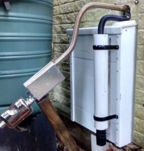
Prototype inlet silencer attached to a cupboard covering the fuel tank and pump, and the less successful exhaust silencers (which still need mounting….)
The sound comes from the heater’s combustion chamber, where a second fan whips the burning flame into a bit of a frenzy – think mini blast furnace – with sound emerging from both the hot exhaust pipe and the cool combustion air inlet pipe.
Looking around the web, noise seems to be a common problem with these units. Many folk have posted ways to quieten this, and I join their ranks today with my take on removing inlet noise, and work-in-progress on exhaust noise.
Inlet noise
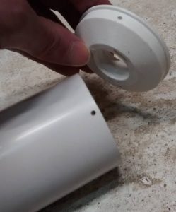 The inlet noise has been completely (I claim…) sorted by a home-brew silencer (white vertical tube in photo above) based on a ~450mm length of 68mm downpipe of the type used with domestic guttering, with two 3d-printed adaptors in the ends: one to take the corrugated aluminium tubing supplied to transport inlet air, and the other (right) to accept the simple muffler (and insect filter?, below left) that came with the heater.
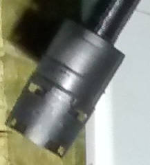 Original air inlet muffler/filter makes the open pipe quieter, but nothing like quiet enough
In the new arrangement, this screws to the bottom of the 68mm pipe (top left photo) to keep insects out (if that was its job), but is not needed at all for silencing.
Inside the 68mm pipe is a length-wise ~28mm (inside) diameter tube just shorter than the 450mm pipe, rolled up around a broom handle from ~10mm pitch galvanised mesh.
Damping comes from polyester fluff wrapped around the mesh tube before the mesh tube and fluff were pushed together into the 68mm pipe. When assembled, the end holes line up with the mesh tube to leave a completely-open central air passage.
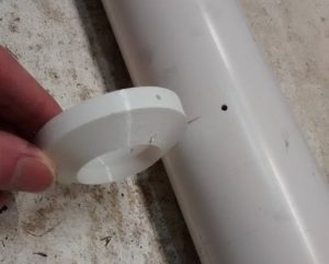 Probably unnecessarily, the 68mm pipe has a 3d printed baffle (left) inside to split the internal length into two unequal parts – to help prevent resonance (a guess), with all the internal surfaces ,ade conical (another guess) to further soften resonant tendencies.
Exhaust noise
My unit arrived without any sort of exhaust silencer, just the corrugated stainless steel pipe seen in the top left photo.
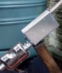 To this I first added a cheap visual (but not functional) copy of a Webasto exhaust silencer (bottom left in photo right). This has a straight-through hole from end-to-end surrounded by a spring stretched from end to end.
Some folk speculate that this spring has some resonance-suppressing effect, but it looks to me that it is intended to keep back glass fibre wadding that was not included before the outer halves were welded together.
Next I added the recently-available ‘upgrade’ muffler (upper right in photo right), available for ~£20 online, which made much more of a difference. Adding both as in the picture (connected by a wrap of aluminium cut from a drinks can and two Jubilee clips) makes it much quieter than the open pipe, but not silent.
The construction of this ‘upgrade’ muffler is interesting. The housing is a rectangular aluminium extrusion and the ends (hardly visible) are identical aluminium castings. Inside is an S-shaped air path defined by two S-shaped perforated half-tubes, also cast from aluminium. Unlike the first filter, this one does have glass fibre wadding wrapped around the outside of the perforated tube.
Adjustment
After installation, even with the standard pipes, the heater must be set-up – a process which I have yet to fully understand.
Analogous to adjusting a carburettor or fuel injection, it requires the fuel-air mixture to be set at different fan speeds ( I believe the heater’s internal computer interpolates for intermediate settings).
As far as I can tell, the best method is to use a carbon monoxide meter, and it needs to be done initially as well as when changes are made to burner-side inlet or exhaust arrangements. It appears that some units come approximately set-up, and others are not set-up at all.
This adjustment is done through the same electronic control panel as setting the fan speed or thermostatic temperature for normal heating use, but it is not the same thing. Not adjusting the finished installation properly could mean excessive CO production, particulates (soot) in the exhaust, internal clogging, internal over-heating, excessive fuel consumption, unexpected flame-outs or low heat output.
If anyone knows where there are clear written instructions for this adjustment, please comment below and I will put a link here.

