An example of a typical industrial environment with multiple electronic applications and rail voltages is a warehouse.
An industrial warehouse can hold complex conveyor systems with many sensors, actuators and control units. Each of these applications has its own requirements in terms of supply voltage, current and installation volume. For example, a surveillance camera with its microcontroller unit and image sensor requires a voltage of 3.3V and current in the Ampere range. The cameras are installed in various positions that often do not have a direct connection to the DC bus and have very limited installation space (Figure 1). Industrial grade inductive sensors are usually connected directly to the DC bus (System 2).
The next step is to evaluate the basics of the DC-DC power module’s switching behaviour to address design challenges.
Switching behaviours
Battery-powered devices do not always operate under full-load conditions. A measurement application, for example, shows a higher current demand during measurement and a lower one between the measurement instances.
These two load conditions are very common. In light load, the application works in idle or standby mode, leading to reduced energy consumption. In heavy load, the application works under nominal conditions, which leads to nominal energy consumption.
The power management system has to be flexible enough to offer the best performance and efficiency during each load situation.
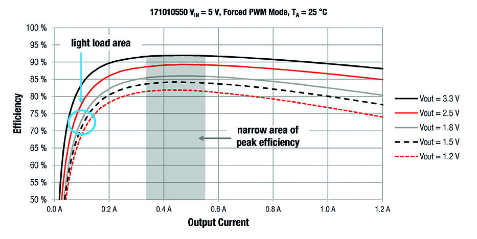 Figure 2 shows the typical behaviour expected from standard buck converters operating in pulse width modulation (PWM) mode, using the 1.2A MicroModule WE MagI3C power module 171010550 as an example. Forced PWM mode is present in the majority of industrial power supplies. It is satisfactory for this type of application as the power supply works in heavy load conditions for the majority of its operating lifetime. Applications such as sensors, however, have a different load situation. Here, light load is the predominant operating condition. The switching behaviour therefore has to be modified to perform optimally during this load situation.
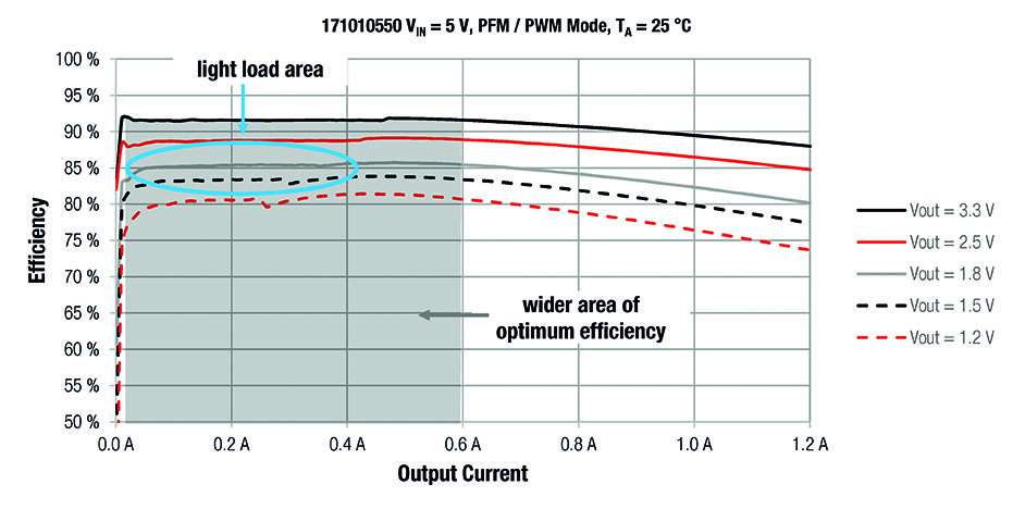 Pulse frequency modulation (PFM) mode offers higher efficiency values as the load current decreases (see Figure 3). This supports a longer lifetime of the battery in battery-powered devices.
The grey Vout = 1.8V curve shows the transition between PFM and PWM modes is around 400mA. The exact point at which the transition happens depends on the chosen output voltage and input voltage.
PFM mode behaviour
Figure 4 compares the inductor current of the module during PWM and PFM behaviour. The inductor current switches in bursts when operating in PFM mode. Both the load and the output capacitor are supplied with energy during each burst. During the idle time (the time between two burst actions) both high side and low side switches are switched off. This leaves the output capacitor to supply the load current by itself. Energy consumption between two burst actions drops dramatically until the feedback system triggers the next burst action.
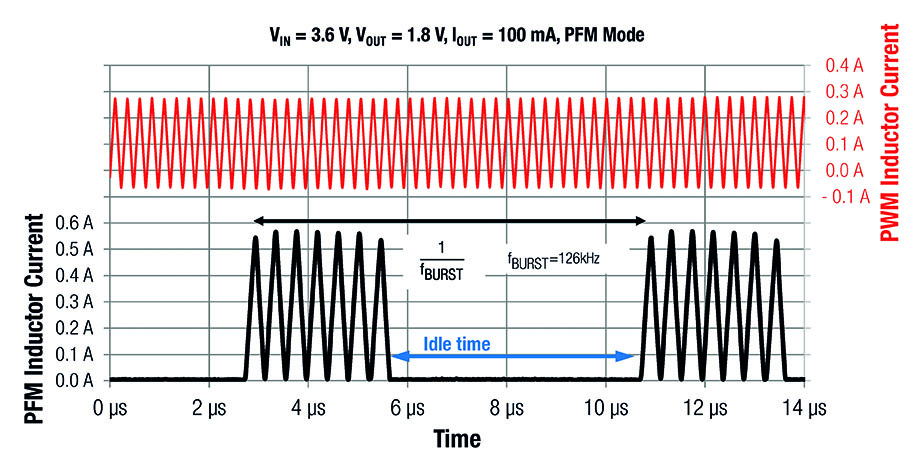 In turn, the efficiency in PFM mode is significantly higher compared to that of traditional PWM mode due to fewer switching losses. The idle time is inversely proportional to the load current, that is, if the load current increases, the time between the burst actions decreases. The module switches back from PFM to PWM mode when the idle time approaches zero, returning to constant switching behaviour at the default switching frequency of 4MHz.
The peak inductor current during PFM mode is higher than in PWM mode, allowing the same amount of energy to be delivered to the load in a fixed period of time while decreasing the losses generated within the converter. During the idle time in burst mode the module produces no losses compared to the PWM mode.
 If the output voltage is higher than a certain value, both switches remain off. The output capacitor is the only supply for the load, which means the output voltage will decrease over the time. When the output voltage drops to a certain level the next burst cycle starts. The resulting value of the ripple depends on the threshold value that is set internally by the controller IC. The output voltage ripple during PFM mode can be reduced by simply increasing the output capacitor.
Industrial environments
Between the standard 24V DC bus and the low rail voltage exists another converter, which converts the high bus voltage to the application voltage (for example, 5V). To evaluate the requirements for a DC-DC converter that is directly connected to the 24V bus, an inductive sensor is a suitable example.
Inductive sensors used to detect metal objects are supplied with 24V input and require 5V for their internal logic. There are two features that are most important for this type of power module. One is the robustness of the power module to short-term changes in the 24V input voltage, or so-called voltage transients. The second is that the DC-DC has to be tiny to fit into an M12 threaded tube while maintaining efficiency to ensure good thermal performance.
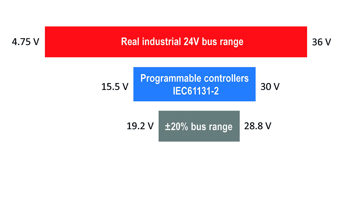
 Classically, the 24V DC bus in the industrial environment is specified to 19.2V to 30V, according to IEC 61131-2.
In reality, various factors play a critical role in how much the 24V deviates from this tolerance range. For example, if the 24V supply line is laid parallel to the control line of a frequency inverter, the pulses are capacitively coupled and the 24V oscillates in the pulse pattern of the frequency inverter.
Similarly, a DC motor connected to the rails will also cause a brief increase in the 24V bus voltage during braking or load shedding. These disturbances can quickly leave the normal range and irreparably damage the connected applications. Figure 5 shows the 24V rail with its tolerances.
The 171930601 MicroModule has been designed by Würth Elektronik to address design concerns with a wide input voltage range of 3.5-36V, adjustable output voltage and thermal performance in a low profile LGA-8 package. It supports up to three solder cycles and is compliant to EN55032 class B/CISPR-32 for low conducted and radiated EMI.
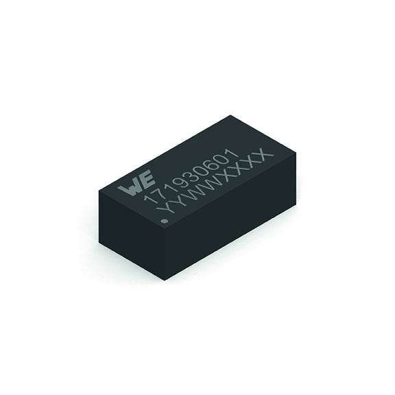 Typical applications include the IoT, sensors and PoL DC-DC converters from 24V, 18V, 15V, 12V, 9V to 5V industrial rails. It can also be used in building control and HVAC systems, advises the company.
About The Author
Timur Uludag is a senior technical marketing manager at Würth Elektronik eiSos Group in the MagI³C power modules business unit