
Overall, it seems like a proper grown-up design with a few quirks.
Power rails are well thought out (see below) and seem well up to the job, and isolation (including power and ground isolation) is fully implemented on-board to separate the microcontroller and USB power domain (together, ‘MCU domain‘ from here)from the cnc-machine-connected power domain (‘cnc-domain‘ from here) – so little chance (that I can see) of current being shoved up the USB into the controlling PC by a fault on the machine side.
Quirks include:
- The three push-button interfaces (hold, run, stop) are wired straight to microcontroller pins with no buffering – not even a resistor: so short wires only and a screened enclosure, maybe. Their counter-terminals are 0V from the MCU power domain.
- The motor driver enable output (ENA on diagram) does not get its own 5V or 0V return output (it is almost as though the case was bought-in, and then the connections were limited to fit the case).
- Cnc domain counter-terminal (and screen) partners to the step and direction outputs are not grounds, but are +5V
- Once the lid is on, there is no way to get wires from any of the JST connectors to the outside world without cutting holes in it.
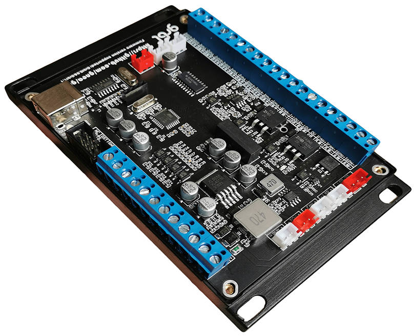
- Not a quirk – but a couple of capacitors were missing from the board
The following information is from rough notes – so check it yourself before relying on it:
Firstly: the non-screw connectors seem to be 2.5mm pitch (not 0.1in) and of the JST XH style.
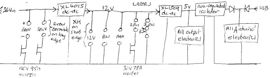 To handle power, there are a couple of dc-dc converters (diagram right – the XL4015 is nominally a 5A part and the XL1509 is 2A) and an un-regulated dc-dc isolator to provide the various voltage rails. The 326P-style microcontroller is fed via a couple of Schottkys from either the USB control/programming mcu domain input, or from 5V derived from the 12 – 36V domain input (called ’36V from here) via galvanic isolation (by a Mornsun B0505LS-1WR2)
The pulse, direction and enable outputs to external drivers (diagram left) are all opto-isolated on-board. This is laudable, although every separate driver I have ever found has opto-isolators on its inputs for these signals, so this is over-kill in many circumstances.
Step and enable outputs (not the direction outputs) are via fast (<1μs) opto-isolators, and all finally emerge finally via cmos buffers powered from the cnc domain 5V, which is directly linked to the main 36V ground.
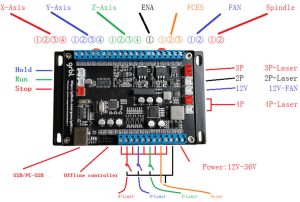
From the diagram, the axes outputs are labelled:
- ‘1’ (DIR+ on pcb) Direction +ve output: connected to +5V from cnc domain
- ‘2’ (DIR-) Direction -ve output: CMOS output relative to DIR+
- ‘3’ (PUL+) Step pulses +ve output: connected to +5V from cnc domain
- ‘4’ (PUL-) Step pulses -ve output: CMOS output relative to PUL+
As mentioned above, the ‘ENA’ enable output to the external drivers does not have its own counter-terminal. Instead has z-axis PUL+ terminal nearby for cnc domain 5V, or the cnc domain 0V which is three terminals the other way.
This 0V is part of the ‘FCES’ group (diagram right) which has:
- ‘1’ (+10V on pcb) ~10V (derived from the cnc-domain 12V, I think)
- ‘2’ (0-10V) analogue output for spindle control, derived from pwm spindle control signal (further down this page)
- ‘3’ (0V) connected directlyto the cnc domain 0V.
Next comes a 36V cnc domain PWM fan output (see circuit diagram above) where the +ve is directly connected to the 36V power input and the -ve is modulated to 0V of cnc domain via a hefty mosfet.
Lastly on that connector is the spindle output and, just like the 36V fan output, the connections are: +ve directly connected to the 36V power input and -ve modulated to 0V from the cnc domain by another hefty mosfet.
Again: this pwm information is also available as the 0-10V analogue signal mentioned above.
The rest of the connections are pretty well described by the power circuit diagram (repeated left) and the annotated board photo (just above).
The x, y and z-limit and probe inputs are all via on-board opto-isolators (simply a 2k4 resistor in series with the input led in each case), and the off-line controller connector appears to be for the simple controllers that are available for small ‘3018’ cnc machines.
For non-USB programming the mcu, there is a row of bare pads on the rear for a bed-of-nails or similar.
Now time needs to be found to wire then thing to the drivers and the steppers on the mill – with all the necessary fans, and other odds and sods.


